Calculating wall surface radiation loads
In this example we ray-trace the total radiated power from a SOLPS simulation and use rectangular observers wrapping around the machine wall to calculate a radiation power profile wrapping around the machine. The full demo file for this tutorial can be downloaded from here. Start by importing all required modules and creating world.
# External imports
import os
import time
import matplotlib.pyplot as plt
import numpy as np
from math import sqrt, pi

# Raysect imports
from raysect.core.workflow import SerialEngine
from raysect.core import translate, rotate_basis
from raysect.optical import World
from raysect.optical.observer.nonimaging.pixel import Pixel
from raysect.optical.observer import PowerPipeline0D
from raysect.primitive.mesh import Mesh
from raysect.optical.material.absorber import AbsorbingSurface

# Cherab imports
from cherab_extra.simulation_data.solps.models.radiated_power import solps_total_radiated_power
from cherab_extra.simulation_data.solps.solps_plasma import SOLPSSimulation
from cherab_aug.integrated_power.wall_detector_geometry import aug_wall_detectors

world = World()

plt.ion()
world = World()
Loading Plasma and machine geometry
Load all parts of the machine mesh from files. We are using a perfect absorbing surface so that no emission will be reflected.
MESH_PATH = '/projects/cadmesh/aug/'

# Load all parts of mesh with chosen material
MESH_PARTS = ['vessel_s02-03.rsm', 'vessel_s04-05.rsm', 'vessel_s06-07.rsm', 'vessel_s08-09.rsm',
              'vessel_s10-11.rsm', 'vessel_s12-13.rsm', 'vessel_s14-15.rsm', 'vessel_s16-01.rsm',
              'divertor_s02-03.rsm', 'divertor_s04-05.rsm', 'divertor_s06-07.rsm', 'divertor_s08-09.rsm',
              'divertor_s10-11.rsm', 'divertor_s12-13.rsm', 'divertor_s14-15.rsm', 'divertor_s16-01.rsm',
              'inner_heat_shield_s01.rsm', 'inner_heat_shield_s02.rsm', 'inner_heat_shield_s03.rsm',
              'inner_heat_shield_s04.rsm', 'inner_heat_shield_s05.rsm', 'inner_heat_shield_s06.rsm',
              'inner_heat_shield_s07.rsm', 'inner_heat_shield_s08.rsm', 'inner_heat_shield_s09.rsm',
              'inner_heat_shield_s10.rsm', 'inner_heat_shield_s11.rsm', 'inner_heat_shield_s12.rsm',
              'inner_heat_shield_s13.rsm', 'inner_heat_shield_s14.rsm', 'inner_heat_shield_s15.rsm',
              'inner_heat_shield_s16.rsm']

machine_material = AbsorbingSurface()  # Mesh with perfect absorber

for path in MESH_PARTS:
    path = MESH_PATH + path
    print("importing {}  ...".format(os.path.split(path)[1]))
    directory, filename = os.path.split(path)
    name, ext = filename.split('.')
    Mesh.from_file(path, parent=world, material=machine_material, name=name)
The core Plasma object will be populated from the output of a AUG SOLPS simulation, this example provided by Felix Reimold (2016). The simulation can be loaded from the AUG MDSplus server or locally from files.
# Load simulation from MDSplus
mds_server = 'solps-mdsplus.aug.ipp.mpg.de:8001'
ref_number = 40195
sim = SOLPSSimulation.load_from_mdsplus(mds_server, ref_number)

# Load simulation from raw output files
# SIM_PATH = '/home/mcarr/mst1/aug_2016/solps_testcase/'
# sim = SOLPSSimulation.load_from_output_files(SIM_PATH)

plasma = sim.plasma
mesh = sim.mesh
plasma_cylinder = solps_total_radiated_power(world, sim, step=0.001)
Description of wall tile observers
Even though we are using the full CAD files for ray-tracing effects such as occlusion and shadowing, we will use a simplified wall surface as the observing surface.
The observing surface will be 1cm wide and covering a complete poloidal cross section of the machine. Each wall element will be a rectangle with x-width=1cm and a y-width that varies poloidally depending on the detail level required in that part of the machine. For example, the observing tiles might need to be much small in the divertor region where radiation gradients are much steeper.
For every tile the minimum description needed is the (xwidth, ywidth) dimensions, a Point3D indicating the centre point of the tile, a surface normal vector, and a y-axis vector. An example description could be a list like this:
# (detector index, xwidth, ywidth, centre_point, normal_vector, y_vector)
aug_wall_detectors = [
    (0, 0.01, 0.2027, Point3D(1.0566, 0.0, -0.072559),
     Vector3D(0.99958, 0.0, 0.028904), Vector3D(0.028904, 0.0, -0.99958)),
    (1, 0.01, 0.06912, Point3D(1.0647, 0.0, -0.20806),
     Vector3D(0.98882, 0.0, 0.14913), Vector3D(0.14913, 0.0, -0.98882)),
    (2, 0.01, 0.1362, Point3D(1.0761, 0.0, -0.31002),
     Vector3D(0.99575, 0.0, 0.092117), Vector3D(0.092117, 0.0, -0.99575)),
     ...
]
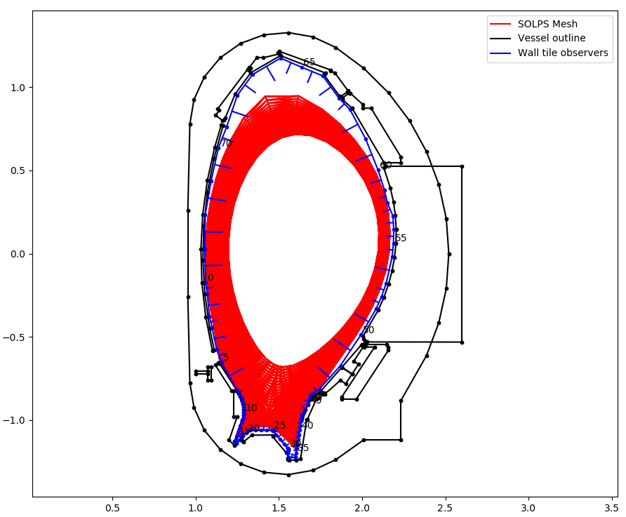
Example wall observation geometry for AUG shown in blue. Surface normals indicated.
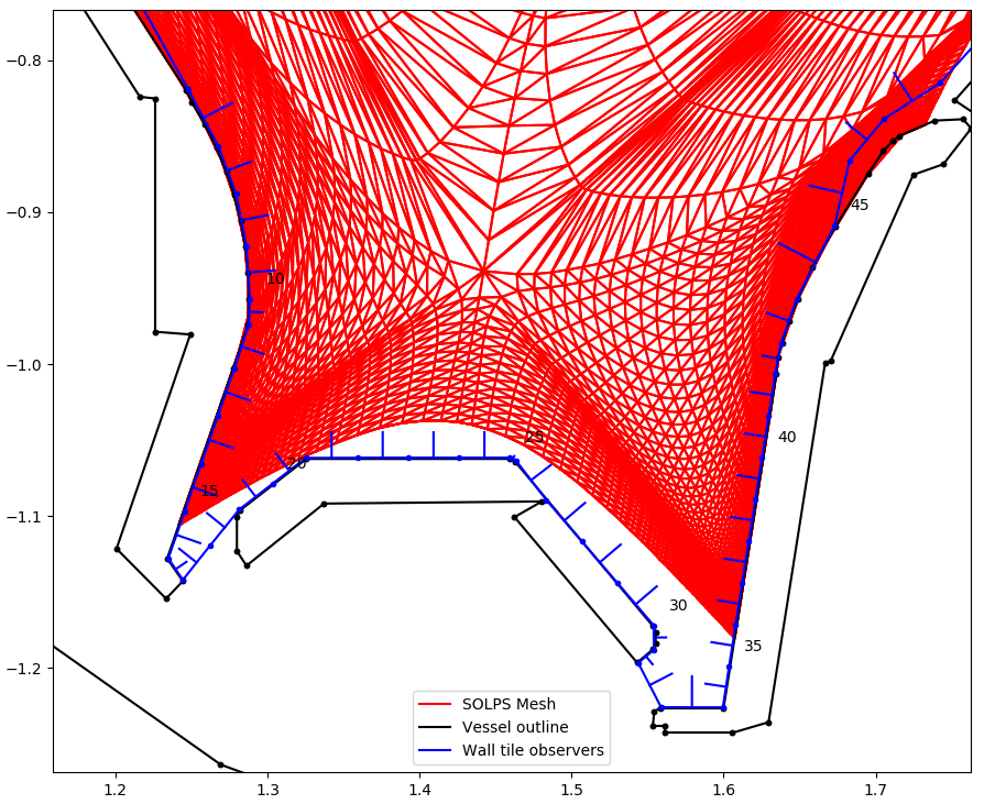
Zoomed in view of the wall observation geometry for AUG in the divertor. Note, observing surface can be very close but must not overlap the CAD files. Otherwise radiation is absorbed by the CAD surface instead of the observing surface.
For each tile in the list of wall tiles, setup the tile as a Pixel observer class. These pixels are rectangular surfaces with arbitrary orientation. Random sample points and vectors are generated across the rectangular surface to cover the full etendue of the tile.
# Storage lists for results
powers = []
power_errors = []
detector_numbers = []
distance = []

X_WIDTH = 0.01  # x-width is constant 1cm
running_distance = 0
cherab_total_power = 0

# Loop over each tile detector
for i, detector in enumerate(aug_wall_detectors):

    print()
    print("detector {}".format(i))

    # extract the dimensions and orientation of the tile
    y_width = detector[2]
    centre_point = detector[3]
    normal_vector = detector[4]
    y_vector = detector[5]
    pixel_area = X_WIDTH * y_width

    # Use the power pipeline to record total power arriving at the surface
    power_data = PowerPipeline0D()

    # Create a affine transform matrix to correctly orientate the tile
    pixel_transform = translate(centre_point.x, centre_point.y, centre_point.z) * rotate_basis(normal_vector, y_vector)
    # Use pixel_samples argument to increase amount of sampling and reduce noise
    pixel = Pixel([power_data], x_width=X_WIDTH, y_width=y_width, name='pixel-{}'.format(i),
                  spectral_bins=1, transform=pixel_transform, parent=world, pixel_samples=500)

    # Start collecting samples
    pixel.observe()

    # Append the collected data to the storage lists
    powers.append(power_data.value.mean / pixel_area)  # convert to W/m^2
    power_errors.append(power_data.value.error() / pixel_area)
    detector_numbers.append(i)

    # Calculate the current poloidal distance around the machine
    running_distance += 0.5*y_width
    distance.append(running_distance)
    running_distance += 0.5*y_width

    # For checking energy conservation.
    # Revolve this tile around the cylindrical z-axis to get total power collected by these tiles.
    # Add up all the tile contributions to get total power collected.
    pixel_radius = sqrt(centre_point.x**2 + centre_point.y**2)
    cherab_total_power += power_data.value.mean * y_width * 2 * pi * pixel_radius
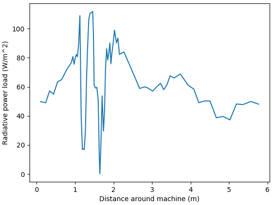
Example plot of radiation power loading around the machine walls.
Checking for energy conservation
We can check that energy is being conserved by looping over each cell in the SOLPS simulation and adding up its power to find the total power emitted in the simulation. Total radiated power should equal total power collected on the walls.
total_rad_data = sim.total_rad_data
vol = mesh.vol
radius = mesh.cr

solps_total_power = 0
for i in range(mesh.nx):
    for j in range(mesh.ny):
        solps_total_power += total_rad_data[i, j] * vol[i, j]

print("Cherab total radiated power => {:.4G} W".format(cherab_total_power))
print("SOLPS total radiated power => {:.4G} W".format(solps_total_power))