Building a Bolometer Camera Using a Mesh and Corner Coordinates
In this demonstration we build a simple bolometer camera from coordinates of the corners of an aperture and 4 foils which are defined in the world’s coordinate system. These define the position and the orientation of the bolometer system. The wall geometry of the camera is provided by an STL mesh file. This information may have been retrived by extracting an STL file or STP file from a CAD model of the machine. The coordinates of the slit and foils could have been read from this model directly using an STL viewing program.
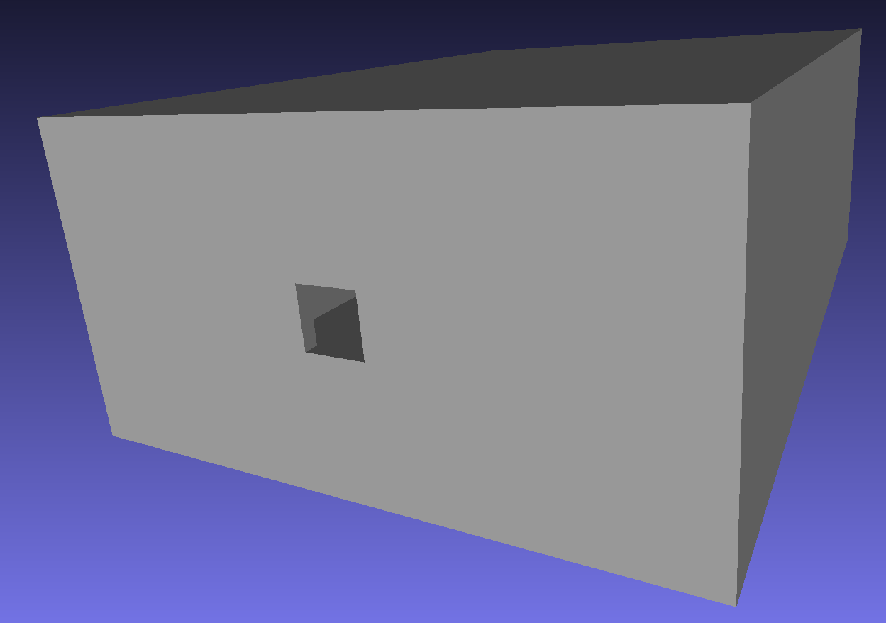
Caption A render of the camera mesh by the meshlab program, showing the rectangular box and aperture. The bolometer foils will be inside the box, but don’t need their own mesh model.
A camera geometry should always be present, else there is the risk that stray light can reach the modelled bolometer foils when it would be blocked by the camera enclosure in a physical system. Using a realistic camera geometry with a suitable material (e.g. metal or carbon) will also permit modelling of reflections inside the camera. In this example we ignore reflections, by making the camera body perfectly absorbing.
Once the camera is designed, we plot the lines of sight of the system. These are calculated by tracing a ray from the centre of the foil through the centre of the slit, and then determining the intersection point on a distant surface. This is a quick and easy way to check the viewing geometry of the detector, but does not show the full 3D field of view of each foil. For that examine the sensitivity matrix demos.
"""
This example demonstrates building a simple bolometer camera where
a mesh representation of the camera body already exists (perhaps
exported from a CAD model), and the coordinates of the slit and sensors
are known in machine coordinates (perhaps read off a CAD model).
The mesh geometry is also in machine coordinates.
"""
import math
from pathlib import Path
import matplotlib.pyplot as plt
import numpy as np

from raysect.core import Point2D, Point3D
from raysect.primitive import Box, import_stl
from raysect.optical import World
from raysect.optical.material import AbsorbingSurface

from cherab.tools.observers import BolometerCamera, BolometerSlit, BolometerFoil

CAMERA_MESH_PATH = Path(__file__).parent / "demo_camera_mesh.stl"

world = World()

########################################################################
# Define the coordinates of the corners of the slit and foils
########################################################################

SLIT_CORNERS = [Point3D(1.002, 0.008, 0.470),
                Point3D(0.998, 0.008, 0.470),
                Point3D(0.998, 0.012, 0.470),
                Point3D(1.002, 0.012, 0.470)]

FOIL_CORNERS = [
    [
        Point3D(0.99303, 0.0081, 0.49),
        Point3D(0.99173, 0.0081, 0.49),
        Point3D(0.99173, 0.0119, 0.49),
        Point3D(0.99303, 0.0119, 0.49),
    ],
    [
        Point3D(0.99811, 0.0081, 0.49),
        Point3D(0.99681, 0.0081, 0.49),
        Point3D(0.99681, 0.0119, 0.49),
        Point3D(0.99811, 0.0119, 0.49),
    ],
    [
        Point3D(1.00319, 0.0081, 0.49),
        Point3D(1.00189, 0.0081, 0.49),
        Point3D(1.00189, 0.0119, 0.49),
        Point3D(1.00319, 0.0119, 0.49),
    ],
    [
        Point3D(1.00827, 0.0081, 0.49),
        Point3D(1.00697, 0.0081, 0.49),
        Point3D(1.00697, 0.0119, 0.49),
        Point3D(1.00827, 0.0119, 0.49),
    ]
]


########################################################################
# Build the bolometer camera from these coordinates and the mesh file
########################################################################
def _centre_basis_and_dimensions(corners):
    """Calculate the centre point, basis vectors, width and height given 4 corners."""
    centre = Point3D(
        np.mean([corner.x for corner in corners]),
        np.mean([corner.y for corner in corners]),
        np.mean([corner.z for corner in corners])
    )
    basis_x = corners[0].vector_to(corners[1]).normalise()
    basis_y = corners[1].vector_to(corners[2]).normalise()
    width = corners[0].distance_to(corners[1])
    height = corners[1].distance_to(corners[2])
    return centre, basis_x, basis_y, width, height


camera_box = import_stl(CAMERA_MESH_PATH, material=AbsorbingSurface(),
                        scaling=0.001)  # Mesh units are mm for this stl file
# Instance of the bolometer camera
bolometer_camera = BolometerCamera(camera_geometry=camera_box, parent=world,
                                   name="Demo camera")
# The bolometer slit in this instance just contains targeting information
# for the ray tracing, since we have already given our camera a geometry
# The slit is defined in the local coordinate system of the camera
slit_geometry = _centre_basis_and_dimensions(SLIT_CORNERS)
centre, basis_x, basis_y, width, height = slit_geometry
slit = BolometerSlit(slit_id="Example slit", centre_point=centre,
                     basis_x=basis_x, dx=width, basis_y=basis_y, dy=height,
                     parent=bolometer_camera)
for i, foil_geom in enumerate(FOIL_CORNERS):
    foil_geometry = _centre_basis_and_dimensions(foil_geom)
    centre, basis_x, basis_y, width, height = foil_geometry
    foil = BolometerFoil(detector_id="Foil {}".format(i + 1),
                         centre_point=centre,
                         basis_x=basis_x, dx=width,
                         basis_y=basis_y, dy=height,
                         slit=slit, parent=bolometer_camera, units="Power",
                         accumulate=False)
    bolometer_camera.add_foil_detector(foil)


########################################################################
# Show the lines of sight of this camera, tracing them from the foils to a
# plane at z=0.4
########################################################################

Box(lower=Point3D(-10, -10, 0.39), upper=Point3D(10, 10, 0.4), parent=world,
    material=AbsorbingSurface(), name="Z=0.4 plane")


def _point3d_to_rz(point):
    return Point2D(math.hypot(point.x, point.y), point.z)


fig, ax = plt.subplots()
for foil in bolometer_camera:
    slit_centre = foil.slit.centre_point
    slit_centre_rz = _point3d_to_rz(slit_centre)
    ax.plot(slit_centre_rz[0], slit_centre_rz[1], 'ko')
    origin, hit, _ = foil.trace_sightline()
    centre_rz = _point3d_to_rz(foil.centre_point)
    ax.plot(centre_rz[0], centre_rz[1], 'kx')
    origin_rz = _point3d_to_rz(origin)
    hit_rz = _point3d_to_rz(hit)
    ax.plot([origin_rz[0], hit_rz[0]], [origin_rz[1], hit_rz[1]], 'k')
ax.set_xlabel("r")
ax.set_ylabel("z")
ax.axis('equal')
plt.show()

Caption The positions of the foils (“x”), the slit (“.”) and the lines of sight for a simple bolometer camera, plotted in the R-Z plane.